Raspberry PI 2 and analog input
Compare to Arduino, Raspberry PI 2 doesn’t have analog pins and even PWM pins. If you check IoT extension for Universal Windows Platform you will discover three sets of classes: I2C, SPI and GPIO. The last one allows to use Raspberry GPIO for sending/receiving high or low voltage only. So, if you want to create a drone or cool robot based on Raspberry Pi 2 and powered by Windows 10, you need to answer the following questions:
· How to read analog signals;
· How to emulate PWM (pulse width modulation);
· How to read digital signals from various digital sensors (if these signals are not LOW or HIGH);
In this post I am going to answer the first question.
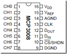
Because GPIO of Raspberry doesn’t have any PWM features we need to use external convertors which help us to transform analog signal to digital. I would recommend to use convertors from Microchip Technology and there is the great selection of different chips: MCP3002, MCP3008, MCP3208 etc. I bought MCP3008 because it supports up to 8 channels and represent analog data in 10 bits format. Because Arduino and Netduino use the same format (from 0 to 1024) I am used to using 10 bits.
MCP3008 works based on SPI bus, so we should use SPI bus on Raspberry. In order to do it I connected CLK leg of the chip to pin SPI0 CSLK (19), D(out) leg to SPI0 MISO pin (21), D(in) leg to SPI0 MOSI (23) and CS/SHDN to SPI0 CS0 (24). V(dd) and V(ref) legs I connected to power and DGND to the ground.
I have analog photoresistor sensor only. So, I used just channel 0 and connect signal leg of the sensor to CH0.
Below you can find my code which you can copy and paste to MainPage.xaml.cs of your Universal application. I didn’t make any interface and just used Debug class to print sensor’s data to Output window:
byte[] readBuffer = new byte[3];
byte[] writeBuffer = new byte[3] { 0x06, 0x00, 0x00 };

private SpiDevice spi;

private DispatcherTimer timer;

private void Timer_Tick(object sender, object e)
{
    spi.TransferFullDuplex(writeBuffer, readBuffer);
    int result = readBuffer[1] & 0x07;
    result <<= 8;
    result += readBuffer[2];
    result >>= 1;
    Debug.WriteLine(result.ToString());
}

protected async override void OnNavigatedTo(NavigationEventArgs e)
{
    await StartSPI();
    this.timer = new DispatcherTimer();
    this.timer.Interval = TimeSpan.FromMilliseconds(500);
    this.timer.Tick += Timer_Tick;
    this.timer.Start();
    base.OnNavigatedTo(e);
}

private async Task StartSPI()
{
    try
    {
        var settings = new SpiConnectionSettings(0);
        settings.ClockFrequency = 5000000;
        settings.Mode = SpiMode.Mode0;

        string spiAqs = SpiDevice.GetDeviceSelector("SPI0");
        var deviceInfo = await DeviceInformation.FindAllAsync(spiAqs);
        spi = await SpiDevice.FromIdAsync(deviceInfo[0].Id, settings);
    }
    catch (Exception ex)
    {
        throw new Exception("SPI Initialization Failed", ex);
    }
}


Leave a comment