Archive for November 2014
Internet of Things: My first experience with Galileo (part 3)
Published on MSDN Blog. Please, visit it for more great articles from Canadian DX team.
In the previous post we developed our first device based on digital outputs from Galileo board. Today I am going to show emulation of analog outputs.
But before we will start to create something I want to return to question about electric schemas. Frankly speaking I am not sure if I want to learn all symbols related to schemas but at the same time we need a tool which will help us show design of our schemas. In order to do it I am going to use a free, open-source application called Fritzing. This application was developed by University of Applied Sciences in Potsdam, Germany. You can download the tool here: http://fritzing.org and it contains links to versions for operation systems like Windows, Linux and OS X.
It’s too easy to recognize needed components, put them to a breadboard and understand if your circuit is completed. Just drag and drop needed components from the parts section to breadboard and connect them in order to make a route.
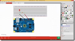
I tried to create a schema for the previous example and you can see the result below:
If you are not able to find some components here you can make search in Internet. For example, I found a better look of Galileo board on Intel Community site. I just clicked the Mine tab and imported “.fzpz” file there.
So, I just used Fritzing in order to show our next example.
Here we are going to use RGB LED in order to show digital outputs in pulse mode. RGB LED is able to show different colors based on RGB schema (R – red, G – green, B – Blue) and it allows different voltage for each lead (the longest lead relates to the ground; the shortest lead, near the ground, relates to red; the shortest lead, on opposite side, relates to blue color; last one relates to green). As I mentioned in the previous post, we are able to emulate analog output using the digital pins with mark “~”. So, let’s connect each lead of RGB LED to appropriate pins (like the image shows) and complete the circuit. We will need more 330 Ohm resistors in order to resist our voltage.
In order to emulate analog output we should use analogWrite method instead of digitalWrite. This method allows to vary parameter from 0 to 255 instead of High/Low and looks very simple in our example. This code will help to show basic color with RGB LED. It will help you to test your circuit and later you can change the parameters of color method in order to generate different colors.
#include "stdafx.h"
#include "arduino.h"

int _tmain(int argc, _TCHAR* argv[])
{
    return RunArduinoSketch();
}

const int redPin = 6;
const int greenPin = 5;
const int bluePin = 3;

void setup()
{
    pinMode(redPin, OUTPUT);
    pinMode(greenPin, OUTPUT);
    pinMode(bluePin, OUTPUT);
}

void color(unsigned char red, unsigned char green, unsigned char blue)
{
    analogWrite(redPin, red);
    analogWrite(bluePin, blue);
    analogWrite(greenPin, green);
}

void loop()
{
    color(255, 0, 0); // turn the RGB LED red
    delay(10000);
    color(0, 255, 0); // turn the RGB LED green
    delay(10000);
    color(0, 0, 255); // turn the RGB LED blue
    delay(10000);
}
In the next article I am going to talk about digital and analog inputs and we will create more examples there.
Kinect 2 and Unity 3D: How to…
In one of my earlier posts I already told about my first experience in Kinect and Unity integration. But at that time I was able to download only the beta version of the package, which didn’t support Face, Face HD and Fusion APIs there. Today, we have access to a release version of Kinect for Windows SDK 2.0 as well as access to Unity Pro packages and if you want to download them right now, you can find all needed links here http://www.microsoft.com/en-us/kinectforwindows/develop/downloads-docs.aspx.
Of course, you still need a Unity Pro for Kinect functionality but if you want to test some features right now, it’s easy to activate 30-days trial version of Unity Pro. It should be enough in order to understand some features of the Kinect as well as to decide if you want to start a business right now.
So, if you already downloaded the Unity Pro package, you could notice that it contains three packages inside (.unitypackage files). The first file Kinect.2.0.1410.19000.unitypackage contains base functionality of Kinect SDK for Unity. It will allow to track bodies, leans, colors and so on. But if you want to use functionality, which relates to face (emotions, face HD tracking etc.) you will need the second package – Kinect.Face.2.0.1410.19000.unitypackage. The last package contains API which will help to use data from Visual Gesture Builder in order to simplify a way to understand predefined gestures.
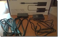
Before I start to create some code, I want to drag your attention to the hardware part. In order to start working with Kinect 2 SDK you need a Kinect 2 sensor. I know that the last sentence looks stupid but it’s realityJ I just found in Microsoft Store that Kinect 2 for Windows costs around 200 dollars – it’s very expensive, if you just want to test something. But Microsoft announced a solution of this problem as well. If you have Kinect for Xbox One, you will able to buy a special Kinect adapter for Windows, which will allow you to connect existing sensor to PC. The adapter costs around 50 dollars, which is much cheaper than a new Kinect sensor. Because I already have Xbox One, I decided to buy adapter only.
The adapter has a pretty big box, because it’s not just connector to USB. In general, Kinect requires more power than USB can provide, so the adapter allows to connect Kinect to power as well.
Because we already discussed some hardware questions I want to point to some additional requirements there. In order to build something with Kinect you will need to have Windows 8 (x64) operation system, USB 3.0 host controller and DirectX 11 capable graphics adapter.
Finally, we finished with hardware, so let’s create some code.
Let’s start with simple example where we will make some manipulation with cube using the base API. In order to do it I created a new Unity Pro project and imported Kinect.2.0.1410.19000.unitypackage there. Let’s put a cube in front of camera and create a script, which should be associated with the cube. We are going to do all work inside that script.
First of all we need to create some data fields in our class:
private KinectSensor _Sensor;
private BodyFrameReader _Reader;
private Body[] _Data = null;
We are going to use KinectSensor in order to access to Kinect. KinectSensor class provides some properties, which allows us to get sources’ references. Kinect supports several sources:
· BodyFrameSource – provides basic information about tracked people (up to 6) like skeleton information, leans, hand states etc.;
· AudioSource – allows to track a sound source from a specific direction;
· BodyIndexFrameSource – shows if a particular pixel relates to body or to background;
· ColorFrameSource – gets a copy of video image, which Kinect got from the camera;
· DepthFrameSource – each pixel of this frame represents a distance between Kinect and tracked objects (up to 4.5 meters);
· InfraredFrameSource – supports black and white frame, which looks good with any sources of lights;
· LongExposureInfraredFrameSource – looks like infrared frame but it supports better quality with less noise. It requires a longer period of time in order to get data;
All of these properties support OpenReader method, which returns the appropriate reader. KinectSensor also supports OpenMultiSourceFrameReader, which allows to get data from several readers just using a single line of code.
Since we need to know basic body movements only, we will use just BodyFrameReader. Additionally, we need an array of Body class in order to store current information about the body.
Right now we are ready to write some initialization methods. Unity supports Start method for MonoBehaviour classes in order to provide a place for initialization. We will use this method to prepare out Kinect and reader.
void Start ()
{
    _Sensor = KinectSensor.GetDefault();

    if (_Sensor != null)
    {
        _Reader = _Sensor.BodyFrameSource.OpenReader();

        if (!_Sensor.IsOpen)
        {
            _Sensor.Open();
        }
    }
}
In the previous post about Kinect I created bad code and forgot to dispose my objects. It worked fine there but if you make the same mistake here you will be able to get data from Kinect just for the first launch of your game inside Unity. After it you will not able to get any data as well as exceptions or something like it. So, in order to avoid having to restart Unity every time when you launch your application inside, we should include OnApplicationQuit method as well. We will call Dispose method for our objects there.
void OnApplicationQuit()
{
    if (_Reader != null)
    {
        _Reader.Dispose();
        _Reader = null;
    }

    if (_Sensor != null)
    {
        if (_Sensor.IsOpen)
        {
            _Sensor.Close();
        }
        _Sensor = null;
    }
}
Right now we are ready to implement Update method, which will be called on each frame update. This method will contain less Kinect related code. We need to get last frame using AcquireLatestFrame method and, in case if frame exists, we need to initialize Body array. Because Kinect supports up to 6 bodies, we need to create array based on this number but BodyFrameSource supports BodyCount property as well.
Please, don’t forget to dispose frame right after initialization of Body array.
Additionally, we should understand if at least one body was tracked. In order to do it we may use IsTracked property in Body class. If at least one body is tracked we will use its index in order to start moving our cube. Here is my version of the Update method:
void Update()
{
    if (_Reader != null)
    {
        var frame = _Reader.AcquireLatestFrame();

        if (frame != null)
        {
            if (_Data == null)
            {
                _Data = new Body[_Sensor.BodyFrameSource.BodyCount];
            }

            frame.GetAndRefreshBodyData(_Data);

            frame.Dispose();
            frame = null;

            int idx = -1;
            for (int i = 0; i < _Sensor.BodyFrameSource.BodyCount; i++)
            {
                if (_Data[i].IsTracked)
                {
                    idx = i;
                }
            }
            if (idx>-1)
            {
                if (_Data[idx].HandRightState != HandState.Closed)
                {
                    horizontal =
                        (float)(_Data[idx].Joints[JointType.HandRight].Position.X
                        * 0.1);
                    vertical =
                        (float)(_Data[idx].Joints[JointType.HandRight].Position.Y
                        * 0.1);

                    if (firstdeep == -1)
                    {
                        firstdeep =
                            (float)(_Data[idx].Joints[JointType.HandRight].Position.Z
                            * 0.1);
                    }
                    deep =
                        (float)(_Data[idx].Joints[JointType.HandRight].Position.Z
                        * 0.1) - firstdeep;

                    this.gameObject.transform.position = new Vector3(
                        this.gameObject.transform.position.x + horizontal,
                        this.gameObject.transform.position.y + vertical,
                        this.transform.position.z + deep);
                }
                if (_Data[idx].HandLeftState != HandState.Closed)
                {
                    angley =
                        (float)(_Data[idx].Joints[JointType.HandLeft].Position.X );
                    anglex =
                        (float)(_Data[idx].Joints[JointType.HandLeft].Position.Y);
                    anglez =
                        (float)(_Data[idx].Joints[JointType.HandLeft].Position.Z);

                    this.gameObject.transform.rotation =
                        Quaternion.Euler(
                        this.gameObject.transform.rotation.x+anglex * 100,
                        this.gameObject.transform.rotation.y+angley * 100,
                        this.gameObject.transform.rotation.z+anglez * 100);
                }
            }
        }
    }
}
As you can see, I used HandLeftState and HandRightState in order to change properties of cube. User will be able to “close” his hand in order to avoid cube movement. In order to use z axis I initialize deep variable in current position of user’s hand by z because the axis shows distance between Kinect and user’s hand. But thanks to that initialization I am able to move cube backward or forward by z.
Next time we will create more advanced examples based on DepthFrameSource and AudioSource.
Azure Mobile Services: Creating a Universal Application
Windows Notification Service and Windows Runtime
It’s time to start developing a real application, which will have a user-friendly interface, implement several types of notifications and be ready for the Store. I don’t have experience in Android and iOS development, so I will try to develop just Windows Phone and Windows 8 applications and I will publish them to the Microsoft Store.
In the previous posts, we developed a Windows Phone (Silverlight) application without a specific interface and we used Microsoft Push Notification Service (MPNS) in anonymous mode, which is good for testing only. Today we are going to use Windows Notification Service (WNS), which is supported by Windows Runtime.
Windows Runtime was introduced almost three years ago as a platform for Windows Store applications with Modern User Interface (Modern UI). It was presented as a new, native, object-oriented API for Windows 8, which helps to develop touch-enabled applications for ARM, x86 and x64 devices. At that time Windows Phone supported Silverlight only for business applications and developers had to develop different types of applications for Windows 8 and Windows Phone. Therefore, developers were waiting for Windows Runtime implementation for Windows Phone, and it was announced this year for Windows Phone 8.1. So, today, developers can share code between WP and Windows applications and use many of their features in the common way. One of these features is Windows Notification Service, which was shared between two platforms and substituted MPNS in WP.
In this post, we will use Universal Apps template to develop both types of applications and we will share as much code as possible. We will use WNS in order to send three types of notifications.
Before we will start coding, we should configure Windows Application Credentials in our Mobile Service (Push tab) but it requires Store registration. So, if you don’t have a Store account yet it’s right time to create it. In order to make an account you may visit the following site https://devcenterbenefits.windows.com/ and you will be able to get free access to Dev Center dashboard.
If you have an account in the Store, you should go to dashboard and try to submit a new Windows Store application (I know that we haven’t developed it yet). During the submission process, you will reserve application name and provide selling details. But we need the next step, which will help to generate client secret key for our application. Let’s click Live Service site link there.
You will be redirected to App Settings page, where you can find a Package SID, Client ID and Client secret.
This information is required to send notifications to registered devices. So, copy these keys and put them to identity tab of Media Services.
Additionally, I want to make several remarks here.
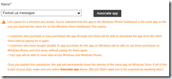
First of all, today we have a chance to associate our Windows Phone and Windows 8 applications. In this case they will use the same notification identities as well as many other features. In order to create the association, you need to visit Windows Phone dashboard and try to submit a new application. In the first step you will be able to select the name, which you already reserved in Windows Store. You should click “Associate app” button in order to make association between our Windows 8 and Windows Phone applications.
Right after you have reserved names for your applications in Windows Store and Windows Phone Store, you may download all needed information to your Visual Studio project as well. If you forget to do it, you will not be able to test your applications because they will not be able to receive notifications due to wrong package identity. In order to do it you may use the context menu for each of our projects.
Server-side for Windows Runtime application
We finished configuring Media Services but in order to enable server-side messages to registered devices we need to modify our Insert trigger. In the previous article, we implemented a simple JavaScript trigger, which was able to send notifications through MPNS. Let’s substitute MPNS to WNS. Additionally, I am going to add more notifications types like RAW and Tile notifications. RAW notifications allow to receive notifications when an application is active and it allows to update content of the application in real time. Tile notifications are used for application Tile update.
Below you can find code, which allows to send Toast notifications, Tile notifications we will add later.
function insert(item, user, request)
{
    request.execute(
    {
        success: function()
        {
            push.wns.sendToastText02(null,
            {
                text1:"Football.ua",
                text2:item.text
            },
            {
                success: function (pushResponse)
                {
                    console.log("Sent push:", pushResponse);
                }
            });

            request.respond();
        }
   }
 );
}
When we used MPNS, we called just sendToast method but Windows 8.1 as well as Windows Phone 8.1 allow different presentations of Toast and Tile notifications. In this application, I decided to use ToastText02 template, which will show text1 as a title of notification (single line) and text2 as a body of notification (two lines on the screen). You can use any other format for your applications, which can be found here.
Interface of our application
Right now, we are ready to create our client application. At the first step, we should allow Toast capabilities in our application. We can make it in the manifest file of the application (Package.appmanifest). In order to do it you can use manifest designer (just click the manifest) but you should be very careful because Universal Apps template will not allow to create a single application for both platforms. Instead you will have two projects as well as two applications. That’s why you should make your modifications inside each manifest (inside both projects). Just click the application tab and set Toast capable to Yes.
Windows 8 and Windows Phone 8.1 don’t require to create own settings page in order to allow user to switch off/on notifications. Windows 8 will generate off/on option inside Settings charm and Windows Phone supports “notifications+actions” page under Settings menu.
On the next stage, we should add Windows Azure Mobile Services package using NuGet manager. We already did it in the previous posts. In this case, you should do it for both projects. Finally, we are ready to write some code.
We will start with code, which will request a notification channel for our device and will send the channel to our Mobile Services. Because you need to do it every time during the application launch, we will use App.xaml.cs file. By default, this file is shared between Windows Phone and Windows applications. We will not change this behavior because WP and Windows 8 application have the same application model and we will have shared code there.
In order to create a notification channel we will use PushNotificationChannel and PushNotificationChannelManager classes. MSDN says that we should store our notification channel after each request and compare a new channel to the old one in order to avoid sending duplicate to our server-side. However, I decided to avoid this practice. We will get notification channel for our application on every launch event and we will send it to MobileServices at once. We should understand that there might be problem with Internet, so, we will check possible exceptions related to it and, in case of an exception, we will continue to launch our application without any notifications or something else. This type of behavior is justified because we will upload old data on the next stage. So, we will have a chance to notify a user about problem with network. In any case, we cannot use notification channel as a guaranteed way for delivering our messages.
I propose the following method for receiving a notification channel and for registering it in Mobile Services:
private async void CreateNotificationChannel()
{
    try
    {
        PushNotificationChannel channel;

        channel = await PushNotificationChannelManager.
CreatePushNotificationChannelForApplicationAsync();

        MobileServiceClient mobileService =
new MobileServiceClient("https://test-ms-sbaydach.azure-mobile.net/");

        await mobileService.GetPush().RegisterNativeAsync(channel.Uri);
    }
    catch
    {

    }
}
Pay special attention that we don’t use application key on client side. So, you need to modify permission for registration script accordingly.
Right now, we can put the method call to the beginning of OnLaunched event handler and it will allow us to receive Toast notifications at once.
It’s time to implement business logic of our application but I leave it to the next post.
Internet of Things: My first experience with Galileo 2 (part 2)
In the previous article we discussed how to setup your first Galileo board and showed some stuff that you need to deploy applications there. In this article we will try to understand what is Galileo and how we may use it in more advanced projects.
So, Galileo is a powerful development platform with x86 compatible processor, USB, mini-PCI, Ethernet port, 256MB DDR3, SD slot, which may help makers, students and enthusiasts to develop their own projects. Galileo is compatible with Arduino prototyping boards, so developers may use any existing hardware, which could be used with Arduino Uno or something like this. And, of course, Galileo may support not just Linux but Windows platform as well. It allows us to create our software in a friendly environment.
Of course, Galileo is the heart of your device and enables reading some inputs from external world and provides own outputs there. For example in order to get inputs you can use many different sensors, buttons, switches etc. and in order to show some outputs you can use motors, LEDs, relays etc. Thanks to the Ethernet adapter, 3G and WiFi shields, Galileo may communicate with external services and other devices, which are connected to Internet.
Our goal, in this article, is to understand how we may connect external devices to Galileo and how we may start developing something. From this prospective we will start with the most important part of the board for developers – with pins. Galileo 2 contains two sets of pins, which allow us to control inputs and outputs. In every project we are going to work with pins, that’s why their understanding is so important.
Usually we will work with the first set of pins – Digital pins. We may use this set in order to send outputs and receive inputs. You can use these pins for outputs in on/off mode. So, output voltage may have 0V or 5V there. Pay attention that all pins provide 5V voltage but Galileo board has a special switcher, which allows to set board in 3.3V mode in order to guarantee compatibility with some 3.3V shields. We will use just 5V voltage in our devices. If you use this set of pins for inputs, you will have the same range of values there – 0V or 5V.
So, we have 13 pins for digital outputs/inputs. But you can notice that some of these pins have a special mark “~”. This shows that we may use marked pins in order to send signals (outputs) in pulse mode. It allows us to emulate rheostat effect, when we have a way to send just n% of current per unit of time. You can use this effect in order to regulate brightness of LEDs or temperature in your apartment etc.
The second set of pins (A0-A5) is used for input only. But in this case it should be analogue input like data from thermometers, potentiometers, variable resistors etc.
This set of pins is important then we receive data, which describes more than two states. We will use these pins in more advantage projects.
Finally you can find some more pins like POWER, 5V, GND and so on. Some of these pins are used in order to control the board, some pins like 5V and VIN are used as source of current and GND pins are used for the ground.
So, right now we got some knowledge about pins and it’s time to look at development tools for Galileo.
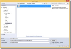
If you already installed VS Extensions for Galileo, you can create projects in C++ based on Galileo Wiring App template. Frankly speaking, Microsoft already included much code there but it allows us to concentrate on device only. Right now we can work with Main.cpp files only. Probably, later, we will dig to code there but today I am going to use already prepared stuff. So, there is the following code in the main.cpp file:
#include "stdafx.h"
#include "arduino.h"

int _tmain(int argc, _TCHAR* argv[])
{
    return RunArduinoSketch();
}

int led = 13;

void setup()
{
    pinMode(led, OUTPUT);
}

void loop()
{
    digitalWrite(led, LOW);
    Log(L"LED OFF\n");
    delay(1000);
    digitalWrite(led, HIGH);
    Log(L"LED ON\n");
    delay(1000);
}
Here there are three functions only. Of course the application will begin with _tmain, which runs RunArduinoSketch functions. The main task of this function is calling setup function and putting loop function inside infinity loop. So, it’s clear that we can use setup function in order to initialize something there and we will use loop function in order to create our runtime logic.
We can see that setup and loop functions are already prepopulated. There is just one call from setup function – pinMode method, which informs our board that we will work with pin number 13. This pin is also connected to a led on the board but we can still use it for external stuff. loop method contains just six lines of code but the most important call there is digitalWrite call. This function allows two parameters like number of pin and state. LOW state shows that we should have 0V voltage and HIGH – 5V.
Let’s use existing code in the template but we will try to use external LED there. In order to do it we need the following components:
· LED – usually LED consumes voltage around 1.7V. So we should resist our 5V voltage there and in order to do it we need a resistor;
· Resistor – in order to resist our voltage we need 330 ohm resistor. It’s time to remember high school and Ohm’s low: I=U/R, where I is current (amperage), U is voltage and R is resistance. So, Galileo board has current in 10 milliamperes and voltage in 5V but we need to select a resistor, which will resist voltage to 1.7V: (5-1.7)/0.01=330. I used a resistor, which contains rings in the following sequence: orange, orange, brown and gold colors. In the next article I will describe how to select the right resistor;
· Breadboard – usually you will use this stuff in order to create a prototype of your final board and it’s good for testing and investigations. You can buy this one separately or find it in many kits;
· 2 wires
Finally, I created this:
In order to understand how it works, you need some information about the breadboard. You can see that our breadboard has several lines that are marked by numbers (from 1 to 30). Pins in each of these lines are connected. So, I used a yellow wire in order to connect pin on my board to pin in line 12 on my breadboard. So, when I put my digital pin to HIGH, current will be in line 12. The resistor connects line 12 and 21, so, we will have 1.7V voltage in line 21. It’s time to connect our LED – put the longer lead (anode) to the same line (21) and put the shorter lead (cathode) to line 23. To the same line (23) connect the blue wire.
Next time I will try to create some schemas but many developers (like me) don’t have knowledge in electrical schemas at all:)
Finally, you can connect yellow wire to digital pin 13 and blue wire to GND pin and just deploy the default application from Visual Studio. Your led should blink. In order to stop the process you can use telnet and tlist/kill commands there.
In the next article we will test more sensors and functions from API.
Internet of Things: My first experience with Galileo 2 (part 1)
Published on MSDN Blog. Please, visit it for more great articles from Canadian DX team.
I didn’t feel so excited since that time, when I bought my first PC – ZX Spectrum. It was a new world, which required strong programming knowledge as well as ability to make research. And today I will open a door to one another new world, where I will try to integrate my programming knowledge with new types of hardware in order to build many new devices. Let’s begin.
First of all, in order to create a new hardware we need to buy some stuff like a board, sensors and wires. Because I have a good experience with Microsoft platform and Visual Studio, I have selected Intel Galileo 2 board, which is supported by Microsoft and it is compatible with Arduino boards, so you will able to find some stuff like sensors, shields, breadboards anywhere. At this time, I don’t have an idea about my future devices, so, I decided to buy a board as well as several starter kits. Finally, I bought my Galileo 2 board, SunFounder 37 modules Arduino Sensor Kit and Sunfounder Project Super Starter Kit.
I used Amazon in order to buy this stuff but you can use any online store. Additionally, I have visited Fry’s Electronics last week and I was too surprised that you may buy a board as well as many of these sensors and components there. There was a huge selection of kits for building own robots, sensors and wires. Probably, there is a special shop in Canada but I am a newcomer in Canada right now. So, please, recommend a good place here and it will help many Canadian developers.
Additionally, you will need a network cable, a microSD card (16 Gb should be enough) and microUSB to USB cable. The last one is used for all modern phones, so it should not be a problem but I forgot to buy a microSD, so I needed to find a nearest Staples in order to buy it. Pay special attention that in order to deploy your application, you need a network cable, which will connect your computer and your board.
Ok, right now, we have a board and some stuff, so we are ready to test the board. In order to use Windows as well as Visual Studio there, you will need to sign a special Windows Developer Program for IoT, which is available here: http://www.windowsondevices.com. You will need to use your Live ID, fill the registration form and right after your application is approved you will get access to Connect site, there you will be able to download all needed software.
In order to set up everything you will need three packages there: WIM image of the operation system, which you will deploy to your board (microSD card); apply-bootmedia.cmd file, which you will use to deploy the operation system; MSI package, which include some tools like Galileo Watcher and Visual Studio integration package.
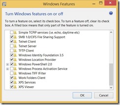
In order to setup your PC you will need to launch the MSI package and enable Telnet features there. Later we will use Telnet in order to kill processes and get some information from the board. In order to enable Telnet features just go to “Program and Features” in the “Control Panel” and call “Turn Windows Features on or off” window.
Right now it’s time to setup your board. In order to do it you need to deploy Windows image to microSD card. Apply-BootMedia.cmd is able to do it for you. Just run the following command in the Command Prompt window (with Administrator permissions):
apply-bootmedia.cmd -destination {YourSDCardDrive} -image {.wimFile} -hostname mygalileo -password admin
Your card will be ready in 2-3 minutes.
Right now, we are ready to run something on Galileo. So, put your microSD card to the slot on the board, use the network cable to connect your Galileo board and turn on your board. Pay attention that Intel provides a universal power supply unit with different connectors. So you will able to use your board anywhere despite of voltage of the local system.
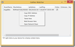
Usually it takes Galileo 2 2-3 minutes in order to start Windows there. During this process you will see blinking LED, which is marked as SD. When LED finishes blinking, your board is ready to communicate with your computer. The second way to understand that the board is ready – launch Galileo Watcher, which will show IP address of your board, MAC address, name and information about state of your board.
Using the Galileo Watcher you are able to monitor the state of your board as well as to launch some stuff like window in browser, which will show existing processes.
Pay attention that if you will use Visual Studio or Telnet in order to connect your board, you will need to provide the name and password there. We provided our password below and the default name is administrator. But, in many cases, you will need to provide the full name of the user like localhost\administrator or mygalileo\administrator, especially, if your computer is in a domain.
Finally, you may launch Visual Studio and create your first project for Galileo 2.
Microsoft provides a ready to go template, which we will discuss next time. Just try to start it on Galileo. If deployment is successful you will see that one more LED is blinking in infinity loop on your board.
In order to kill the process you will need to start Telnet and use the following commands:
· tlist – in order to see all existing processes
· kill <process ID> – in order to kill selected process
Probably I wrote enough for the first part. In the next article we will try to understand, what is Galileo and how to create a simple scenarios there.
Dev Center Benefits: How to join
New life – new developer account in Microsoft Store.
I just moved to Vancouver, BC, so I decided to open my own account in order to publish some Windows Phone and Windows 8 applications. Today, you can pay $20 and get unlimited account there. But from the one hand, I still don’t have a local bank account in Canada, and from the other hand I already heard about a program, which provides some benefits for new developers, who don’t have Store account yet. That’s why I decided to start with https://devcenterbenefits.windows.com/ site.
As you can see, according to the program, every developer has a chance to get many benefits from Microsoft like consulting, priority support, gift cards etc. These are very cool benefits because thanks to them, every developer has a chance to increase quality of his applications as well as get some tools for promo. Probably, later, I will share my experience about each of these benefits but right now I found that I am able to get Free Dev Center account.
Of course, I clicked “Join Now” at once and passed several registration steps there.
In the first step you need to login with existing Live ID or to create a new one.
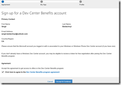
At once as you logged in, you need to accept the program agreement and click “Accept & Continue”.
In the next step you are able to submit links to your application in order to get upgrade to the next level of the Dev Benefits program. Because I just wanted to create a new account I skipped this step. You will be able to add your applications at any time, later.
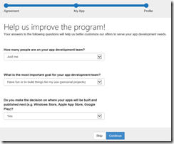
Next step allows you to help Microsoft to understand who you are and what you are going to do on Microsoft platform. You can answer these questions or just skip this step.
Finally, my Dev Benefits account was created and I got access to my offers including free developer account.
Pay special attention there that in order to redeem your registration code, you need to agree that you will publish your first application in 90 days. So, if you are not ready to build your application right now, don’t click the button. If you redeemed you code but didn’t publish the application your offer could be expired (but I didn’t have a way to check it).
Therefore, I spent about 3 minutes in order to get my registration code. Additionally, I spent 2-3 more minutes in order to create my Store account using this code. And CREDIT CARD WAS NOT REQUIRED!

